The I-35 West bridge over the Mississippi River in Minneapolis, Minnesota, consisted of three trussed spans and several beam and post spans typical of 1960's era freeway construction.
Analysis to date here at Free Republic has centered on looking for the triggering cause in the bridge collapse, and the sequence of failure, as determined by available pre- and post-collapse imagery and video.
Efforts so far have been hampered by uncertainty regarding the condition and disposition of the eastern truss panels originally located above and near pier 6. I hope to rectify this uncertainty and shed significant new light into the bridge's failure sequence in this analysis.
Per the 2006 MnDOT Inspection Report, the bridge's piers are numbered south to north, with the bridge's span's also numbered south to north. Since the southern approach begins with the south abutment, pier 1 is situated at the north end of span 1, and at the south end of span two. I will use the same referencing convention throughout this discussion. The full report, and numerous others, are available at:
http://www.dot.state.mn.us/i35wbridge/history.html
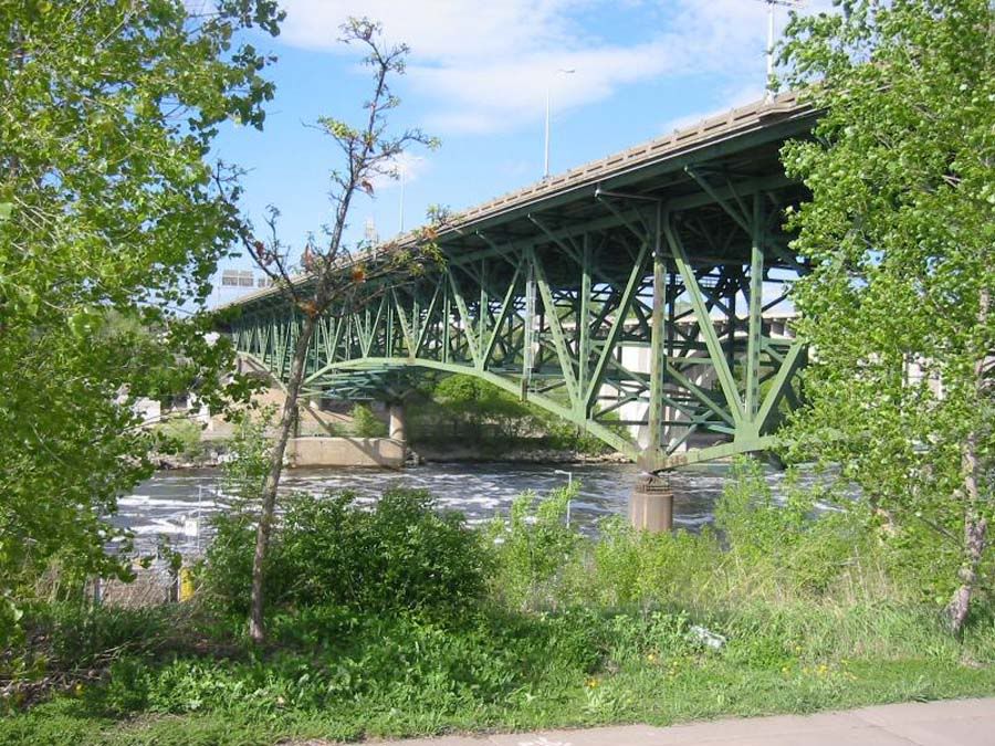
For reference purposes throughout this analysis, here is an image of the bridge prior to collapse, looking northeast, with pier six at center right foreground, span 7 over the river centered, span 8 visible at left, and part of span 6 visible at right:
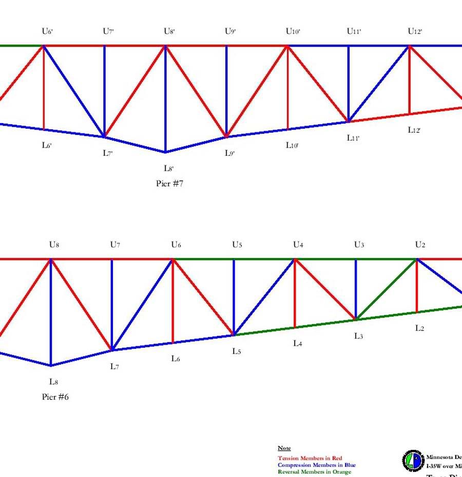
For additional reference, the image below shows the MnDot scheme of truss component identification, used thoughout this analysis:
Early analysis, almost from day one after the collapse, noted that the western truss panels at pier six had rotated to the east on failure, and appeared to retain most, if not all, of their original structural integrity. Later examination indicated that the west truss panels at pier 6 probably separated, partially or fully, from the rest of span 7 prior to this eastward rotation, since the larger part of span 7 did not follow the main trusses east in rotation, as shown below:
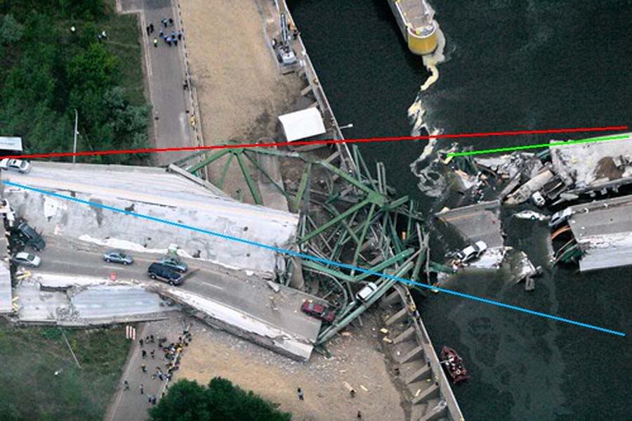
In the above image, the red line indicates the general orientation of the west truss prior to collapse. The blue line indicates the post collapse disposition of the pier 6 panels of the west truss, and the green line indicates the post collapse disposition of the main portion of the span 7 west truss. It is clear from this image that the two post collapse portions of the west truss are unlikely to have dropped while still attached to each other during all phases of the collapse sequence, and that separation probably occurred prior to the pier 6 west truss panels rotation to the east.
At this point in the investigation, suspicion was directed towards the east truss at and just north of pier 6, including, but not limited to the southeast pier 6 kingpost, one of four primary support members for the entire trussed spans. Without knowing the location or disposition of the pier 6 east truss members after the collapse, all such analysis was limited to supposition and speculation.
Additional research of the available imagery, however, was able to locate several of the east trusses' significant structural members, as illustrated and discussed below:
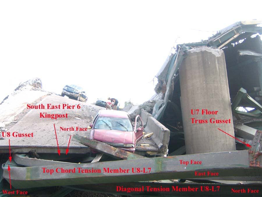
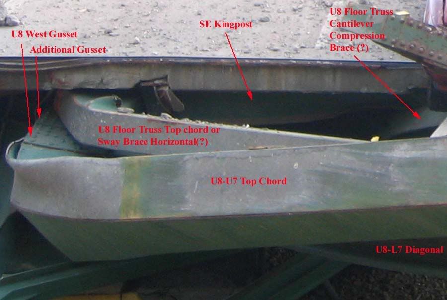
The key to discovery of the post collapse east truss components was the double gusset just visible in the above image, looking south towards the northbound traffic lanes at pier 6. This is typical construction technique, and had been noted in several pre-collapse images of the bridge. On discovery of the double gusset, additional members were located simply by following known east truss members to the next logical attachment points. A digitally enhanced zoom of the above image, clearly showing the doubled U8 connection gussets is shown below:
In the following image, looking west at pier 6, known east truss components are indicated in red, and these are used to identify post collapse east truss members indicated in green.
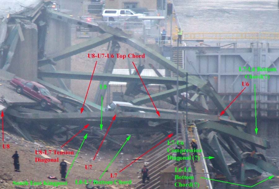
Important aside, note the post collapse disposition of the west truss member corresponding to east truss member L7-L6 in the above image, unmarked but located directly behind the red arrowhead labelled U6. Note particularly the attachment point L7 gussets and damage suffered by the west truss bottom chord in relation to the intact west truss panels, this will be referred to later in this discussion.
Image 6 below, looking west at pier 6 but closer than Image 5 above, add the post collapse location of a critical bridge component, part of the pier 6 east truss roller nest assembly.
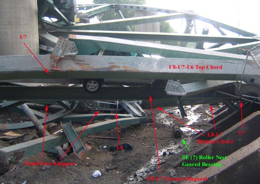
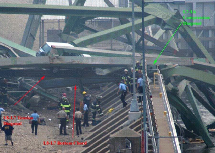
Image 7 below, also looking west at pier 6, notes the probable post collapse disposition of the L7-U6 east truss compression diagonal, or better put, the remnant stub thereof. Also visible in this image, behind the red U8-L7 arrow, is another critical pier 6 component, the southeast rocker bearing plate.
While the above images may be difficult for non-engineers to understand, they are important in establishing a basis for the following image, a post collapse diagram of both main trusses as oriented after the failure sequence was complete.
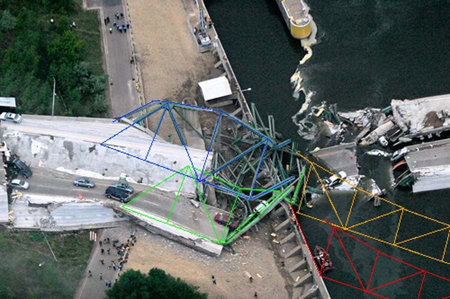
In image 8 above, looking down on pier 6, the known and likely locations of west truss pier 6 components are indicated in blue. The orange lines indicate the "missing" or severed members of the west truss further out into span 7, as they would have appeared had span 7 not severed early in the collapse progression.
Similarly, known or likely locations for east truss pier 6 components are indicated in green, while extensions of same without span 7 separation are indicated in red. These lines were constructed atop the base layer imagery on separate Photoshop image layers, to facilitate construction of the following image, where by the layers are lifted from the previous sub-image layer, rotated and re-oriented to pre-collapse dispositions, for comparison purposes.
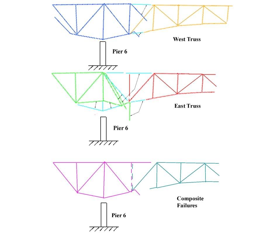
In the above image, Image 9, looking west at pier 6, the two upper panels indicate the west and east trusses, as reconstructed from post collapse imagery, respectively. The blue lines indicate the original positions of members which were located in post collapse imagery, and rotated back into the pre-collapse dispositions.
The lower panel in Image 9 notes the combined post collapse arrangement of both the east and west truss for comparison purposes, and the similarities are striking. With the exception of the U7-L7 strut, the first vertical truss member north of the pier 6 kingposts, both trusses apparantly failed in near identical manner. Noteworthy points of similarity include the U7-U6 top chord severance locations near the U6 connection gusset, the bending moments impressed on both east and west U7-U6 top chord members, the severance locations of both east and west truss L7-L6 bottom chord members, and the bendimg moments impressed on same, and the catastrophic failure at the west truss L7 gusset, specifically the tension and bending loads imposed on the L7-U6 compression diagonal mentioned earlier, which coincide with the apparant severe moments imposed on the east truss's coincident member.
So far, the discussion here has been limited to empirical evidence and my interpretation of same. This is as far as my analysis allows me to proceed without supposition and speculation, however, I am reasonably confident that additional analysis is at least within the bounds of probability and possibility regarding the failure of this bridge.
Put another way, the conclusions I am about to draw cannot, as yet, be substantiated in fact, but neither can they be refuted by the evidence availabe to us at this time. They are well within the realm of structural possibilities as we now know them.
From all analysis to date, we have reason to believe that:
1. Most of span 7 separated from the span 7 pier 6 truss panels prior to east rotation of the pier six truss panels.
2. Video analysis of the failure sequence shows the south end of the bridge falling earlier than the north end of span 7.
3. The east truss at pier 6 mosdt likely lies underneath the west truss at pier 6.
With the benefit of newly discovered data as outlined in this discussion, I offer the following tenative, additional conclusions.
1. Both east and west truss L7-U6 compression diagonals were subjected to severe tensile and bending stresses and shattered near the L7 connection gusset.
2. Both east and west truss U7-U6 top chords were subjected to tensile stresses at or above failure levels early in the collapse progression resulting in separation at or near the U6 connection gusset.
3. Both east and west truss L7-L6 bottom chords were subjected to severe stresses at or near the L6 connection gusset, and both were subjected to bending moments consistent with failure level gravity loads about the L7 connection gusset.
Based on these tenative additional comculsions, I believe it most likely that the east truss U7-U6 top chord failed in tension at or near the U6 connection gusset very early in the collapse progression, quite possibly as the collapse sequence initiating event.
If in fact this key structural member failed as discussed above, a progressive collapse sequence could ensue as follows:
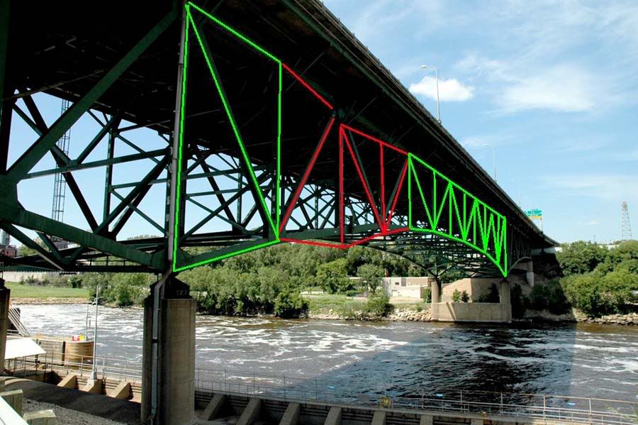
With the east truss top chord severed at U6 as shown in Image 10 above, externally imposed tension loads on U7-U6 go to zero, while internal stress on this member predominates. The upper face of this box beam goes into radical tension while the lower face goes into compression, inducing a bending moment at connection U7, 100% consistent with the post collpase disposition of this member. A similar progression is imposed on the L7-U6 compression diagonal.
Both live and dead span 7 gravity loads are almost immediately transferred to the east truss L7-L6 bottom chord, imposing internal stress on that member similar to that discussed above. It cannot resist the imposed stresses and begins to deflect downwards, as shown in Image 10 above and also indicated by red arrow 1 in Image 11 below.
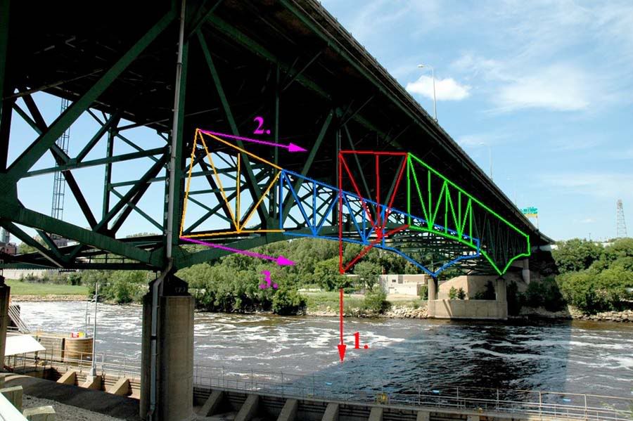
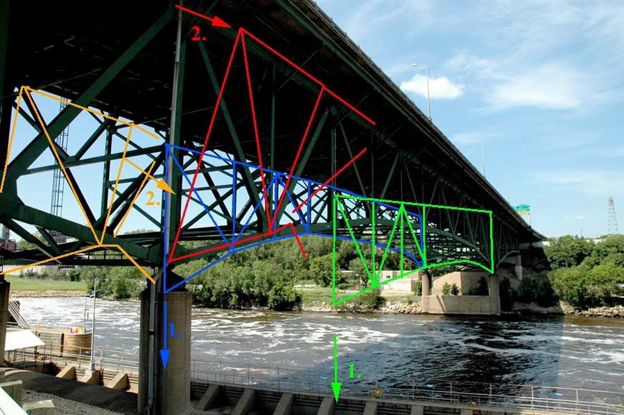
As soon as the east truss L7-L6-L5 bottom chord begins to deflect downwards, significant tensile loads are applied to the horizontal and diagonal sway bracing members at the U6-L6 interface, as indicated by orange arrows 2 and 3 in Image 11 above. These tensile stresses are transferred to west truss members at the swy brace connection points, and are resisted by the both the west truss roller nest/rocker bearing assempbly atop pier 6, and by sway bracing in the horizontal planes co-planar with the west truss top and bottom chords. The vector pair of eaastward tensile stress, and westward resistance to same induces an eastward rotational moment about the west truss bottom chord, transverse (laterally) to its axis.
This rotational moment of the west truss top chord towards the east is transmitted to the now separated pier 6 panels of the east truss via the much more substantial sway bracing atop pier 6 as shown below, by red and orange arrows 2., in Image 12. Both the southwest and southeast kingposts at pier 6 are now in rotation to the east. The main portion of span 7, no longer attached at the east truss top chord, and probably not at the west truss top chord, is subject to much less eastward deflection, by virtue of their bottom chord only attachments to the rotating pier 6 superstructure, however, this rotation imposes severe twisting stresses on both the east and west L7-L6 bottom chord members, again 100% consistent with post collapse imagery data.
Not too far into the rotational failure of the pier 6 superstructure, both bottom chords separate at the L6 connection gussets, and once unsupported at their midspan ends, are nearly severed or completely severed at the L7 connection gusset, 100% consistent with post collapse imagery.
From here, the collapse progression holds little surprise or ambiguity. The pier 6 superstructure continues to rotate eastward, and the rest of span 7's trusswork and road deck, severed from the pier 6 truss panels and unsupported at their south ends, drop straight down into the river. At some point during the sequence, span 6, south of pier 6, having lost the counterbalancing weight associated with the span 7 cantilever compenent, begins to deflect downwards, sagging at midspan, and inducing a smaller but significant rotation to the pier 6 superstructure. This induces the tops of the pier 6 kingposts to rotate a small distance to the south, resisted by the pier 6 roller nest assembl;ies and rocker bearings, and ejects the pier 6 roller nest and rocker bearing components northward from their pro-collapse positions atop pier 6, consistant with their post collapse disposition as evidenced by the available imagery.
Finally, I would repeat that while I cannot prove this is the correct failure sequence, I can say that this sequence is consistent with all available data of which I am aware, and that none of the available data contradicts these assumptions, conclusions and speculations to any appreciable extent of which I am aware. More as new information or imagery becomes available.
Feel free to distribute this analysis for any non-commercial purposes, though I do ask that Free Republic be referenced in all such distributions. All imagery used in this analysis was accessed in the public domain, though original copyrights still reside with the original owners or their designees. Overlying graphics analysis may be distributed for non-profit purposes, with Free Republic referencing as outlined above.
I greatly appreciate all who have contributed to previous discussions regarding this matter, you are too numerous to name but you know who you are. Without your efforts in analyzing this failure, and in bringing imagery and video to my attention, none of this discussion would have been possible.
Thank you.