Great analysis--thanks for piecing it all together. You've certainly nailed the point, mechanism and sequence as to how the main span failed.
Couple Qs.
* If you're feeling motivated (insomnia, perhaps), could you redraw that MnDOT diagram so it shows the whole bridge from one side to the other--I'm still never quite sure which are the center spans and which are the landside-spans. And identify what the "king truss"--I'm not sure what a king truss is on a cantilevered tower.
On the diagram, I'm thinking the L9/U10 member on the MnDOT diagram is actually compression, not tension (a typo for MnDOT's consultant). (like the L7/U6 member). For one thing, the photos show it as being a box beam, not an I beam. For another, the bridge wouldn't stand up if it was tension.
* Do you have an opinion as to whether the U10/L10 area failure was or wasn't the initial failure? If the south landside span failed, the center span would be expected to sag and buckle somewhere, is U10/L10 as good as any spot for that?
i.e. if the south landside arm failed somewhere, then the counterweight would be gone from the main span, and the section from U8 to U10 would suddenly be acting in compression, rather than tension. and you'd get a buckling of the tension member somewhere on that stretch, quite possibly at the farthest-extremity of the tension member.
kwuntongchai wrote:
Great analysis—thanks for piecing it all together. You’ve certainly nailed the point, mechanism and sequence as to how the main span failed.
Couple Qs.
* If you’re feeling motivated (insomnia, perhaps), could you redraw that MnDOT diagram so it shows the whole bridge from one side to the other—I’m still
never quite sure which are the center spans and which are the landside-spans. And identify what the “king truss”—I’m not sure what a king truss is on a
cantilevered tower.
**************
I don’t know about drawing the whole bridge. I’ve got a pretty busy schedule right now as it is, and that’d take some time to do. I know once I got into it, I’d start adding more and more detail, until I’d redrawn the full set of working plans, and I’d also veer off into stress and failure analysis such that a project like that might stretch into years.
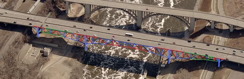
In your post 45 photo, pier 8 is in color at far left. Span 8 starts there and ends at the next pier to the right, pier 7, the north end of the main river span, span 7. Pier 6 is on the right side of the river, and span 6 stretches right from there to pier 5, the farthest right member you’ve highlighted in color, save for that last diagonal.
(There’s a LOT going on at that diagonal, but that’s another book that isn’t written yet. For now, at least note the expansion joint in the road deck above that far right diagonal.)
Kingpost is a vernacular term we’ve always used to refer to the tallest vertical member in a truss. In practice I and the people I’ve worked with usually used it in connection with Pratt or Howe truss designs, in this analysis, we used the term to refer to the vertical members above piers 6 and 7, on either end of the main river span.
Keep in mind, this truss isn’t a pure cantilever either, it is a complex truss, which is about as far as I want to get into that, absent specific questions.
*************
kwuntongchai wrote:
On the diagram, I’m thinking the L9/U10 member on the MnDOT diagram is actually compression, not tension (a typo for MnDOT’s consultant). (like the
L7/U6 member). For one thing, the photos show it as being a box beam, not an I beam. For another, the bridge wouldn’t stand up if it was tension.
*************
I believe you are almost certainly correct here, except the member in question is L9’-U10’, not L9-U10. L9-U10 would be in span 6, south of pier 6, while L9’-U10’ resided north of pier 7 in span 8.
I believe the origin was designated at the center of the main span, span 7, with normal numbered junctions incrementing south from there, and primed numbered junctions incrementing north from there.
*************
kwuntongchai wrote:
* Do you have an opinion as to whether the U10/L10 area failure was or wasn’t the initial failure? If the south landside span failed, the center span would be
expected to sag and buckle somewhere, is U10/L10 as good as any spot for that?
i.e. if the south landside arm failed somewhere, then the counterweight would be gone from the main span, and the section from U8 to U10 would suddenly
be acting in compression, rather than tension. and you’d get a buckling of the tension member somewhere on that stretch, quite possibly at the
farthest-extremity of the tension member
************
In your later posts, you use a connection labelling scheme inconsistent with that used by MnDot, so I’m not completely sure I know what you ask here.
However, your labelling scheme here seems consistent with the rest of your question, and in any event, a general answer will suffice.
If I was to look for a triggering failure anywhwere on the southern approach, the first, (and possibly last) place I’d look would be at the pier 5 endbeam/crossbeam/rockerbearing assemblies, on both the east and west trusses, the far right diagonal in your image, mentioned above.
A lot of significant history there, and I refer you to the 2006 Inspection Report for more detail before getting deeper into this.