Skip to comments.
Minneapolis I-35W Bridge Collapse Failure Analysis
opinion
| 8-21-2007
| jeffers
Posted on 08/21/2007 3:20:52 PM PDT by jeffers
Minneapolis I-35 bridge collapse: Failure Analysis
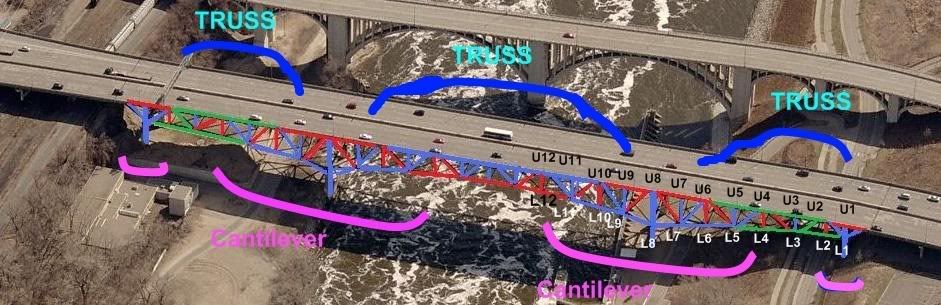
The I-35 West bridge over the Mississippi River in Minneapolis, Minnesota, consisted of three trussed spans and several beam and post spans typical of 1960's era freeway construction.
Analysis to date here at Free Republic has centered on looking for the triggering cause in the bridge collapse, and the sequence of failure, as determined by available pre- and post-collapse imagery and video.
Efforts so far have been hampered by uncertainty regarding the condition and disposition of the eastern truss panels originally located above and near pier 6. I hope to rectify this uncertainty and shed significant new light into the bridge's failure sequence in this analysis.
Per the 2006 MnDOT Inspection Report, the bridge's piers are numbered south to north, with the bridge's span's also numbered south to north. Since the southern approach begins with the south abutment, pier 1 is situated at the north end of span 1, and at the south end of span two. I will use the same referencing convention throughout this discussion. The full report, and numerous others, are available at:
http://www.dot.state.mn.us/i35wbridge/history.html
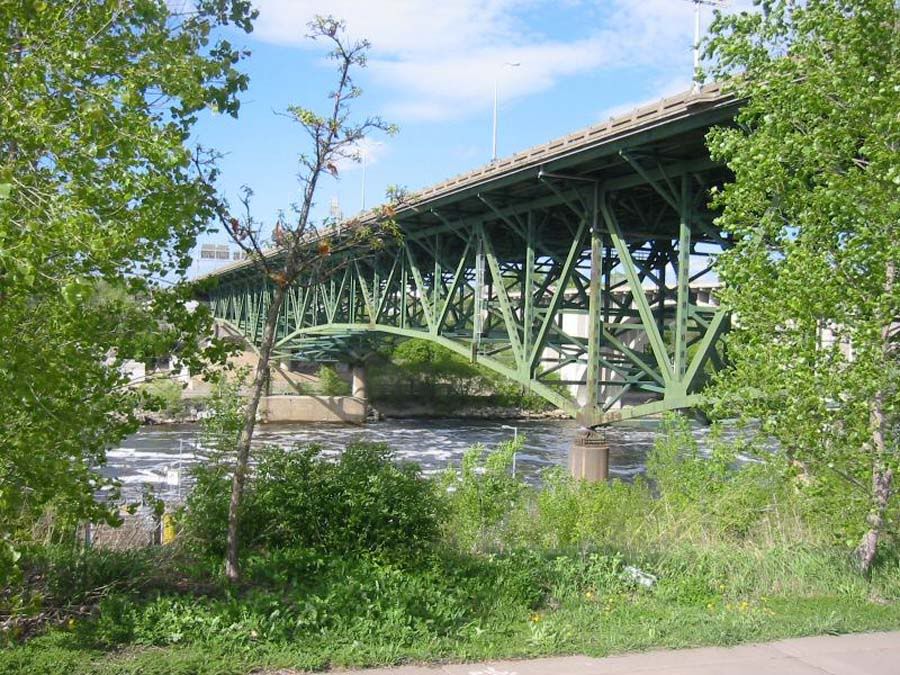
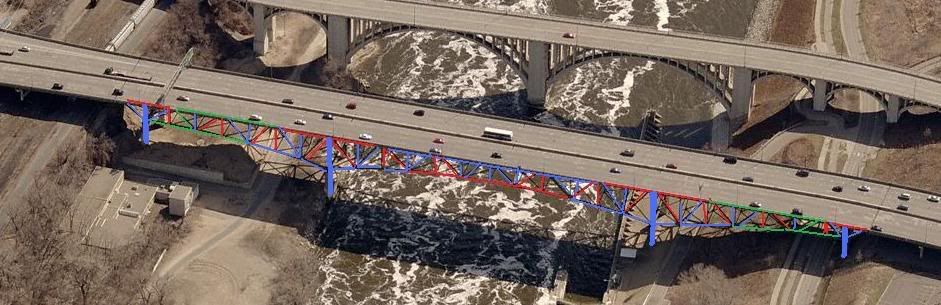
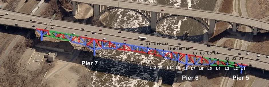
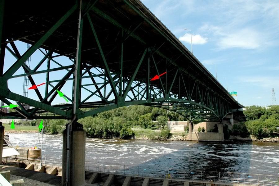
For reference purposes throughout this analysis, here is an image of the bridge prior to collapse, looking northeast, with pier six at center right foreground, span 7 over the river centered, span 8 visible at left, and part of span 6 visible at right:
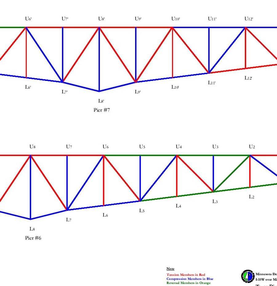
For additional reference, the image below shows the MnDot scheme of truss component identification, used thoughout this analysis:
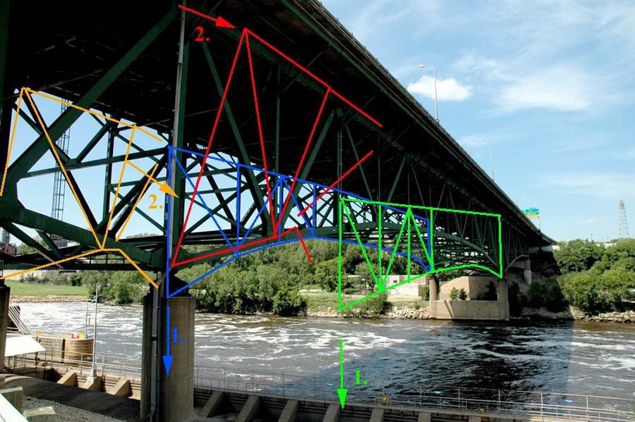
Early analysis, almost from day one after the collapse, noted that the western truss panels at pier six had rotated to the east on failure, and appeared to retain most, if not all, of their original structural integrity. Later examination indicated that the west truss panels at pier 6 probably separated, partially or fully, from the rest of span 7 prior to this eastward rotation, since the larger part of span 7 did not follow the main trusses east in rotation, as shown below:
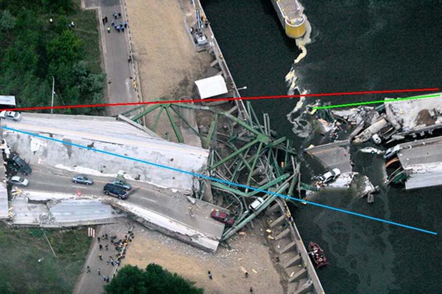
In the above image, the red line indicates the general orientation of the west truss prior to collapse. The blue line indicates the post collapse disposition of the pier 6 panels of the west truss, and the green line indicates the post collapse disposition of the main portion of the span 7 west truss. It is clear from this image that the two post collapse portions of the west truss are unlikely to have dropped while still attached to each other during all phases of the collapse sequence, and that separation probably occurred prior to the pier 6 west truss panels rotation to the east.
At this point in the investigation, suspicion was directed towards the east truss at and just north of pier 6, including, but not limited to the southeast pier 6 kingpost, one of four primary support members for the entire trussed spans. Without knowing the location or disposition of the pier 6 east truss members after the collapse, all such analysis was limited to supposition and speculation.
Additional research of the available imagery, however, was able to locate several of the east trusses' significant structural members, as illustrated and discussed below:
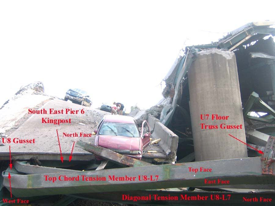
The key to discovery of the post collapse east truss components was the double gusset just visible in the above image, looking south towards the northbound traffic lanes at pier 6. This is typical construction technique, and had been noted in several pre-collapse images of the bridge. On discovery of the double gusset, additional members were located simply by following known east truss members to the next logical attachment points. A digitally enhanced zoom of the above image, clearly showing the doubled U8 connection gussets is shown below:
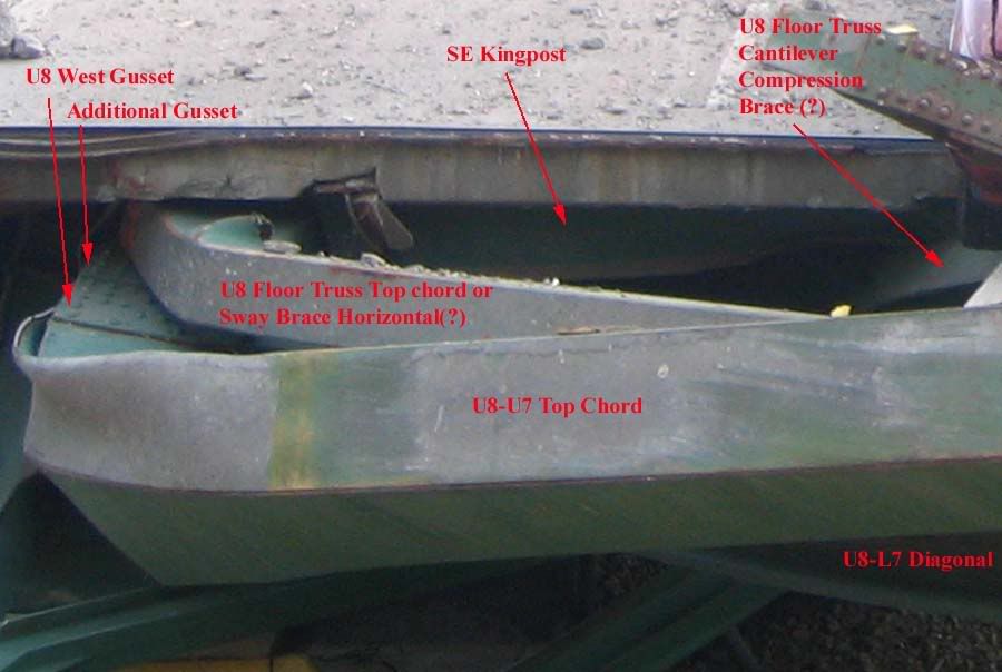
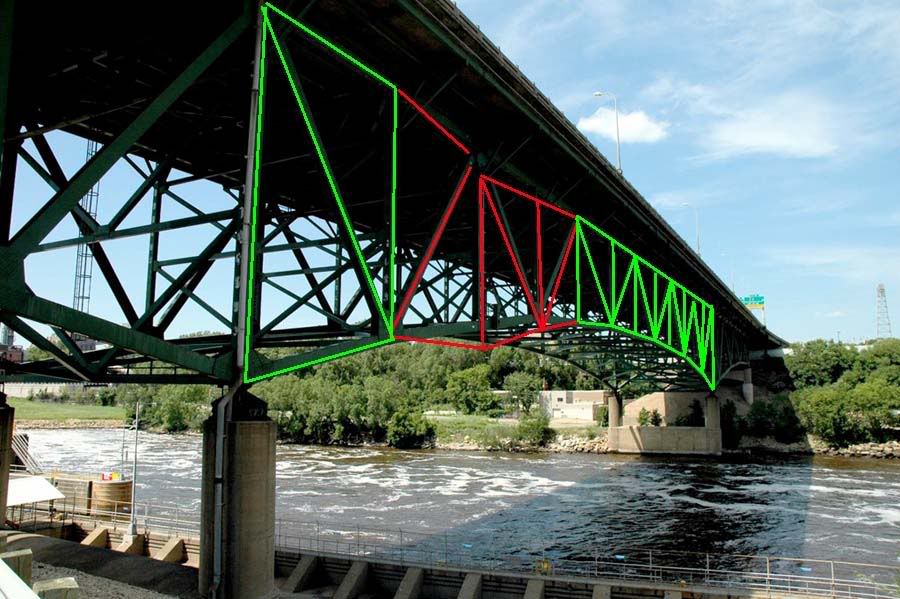
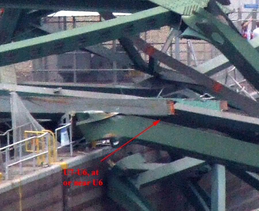
In the following image, looking west at pier 6, known east truss components are indicated in red, and these are used to identify post collapse east truss members indicated in green.
Important aside, note the post collapse disposition of the west truss member corresponding to east truss member L7-L6 in the above image, unmarked but located directly behind the red arrowhead labelled U6. Note particularly the attachment point L7 gussets and damage suffered by the west truss bottom chord in relation to the intact west truss panels, this will be referred to later in this discussion.
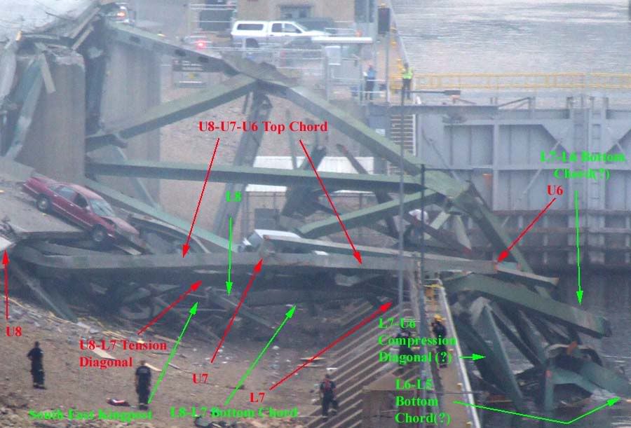
Image 6 below, looking west at pier 6 but closer than Image 5 above, add the post collapse location of a critical bridge component, part of the pier 6 east truss roller nest assembly.
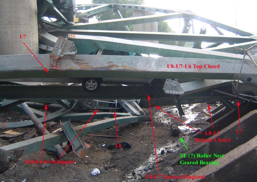
Image 7 below, also looking west at pier 6, notes the probable post collapse disposition of the L7-U6 east truss compression diagonal, or better put, the remnant stub thereof. Also visible in this image, behind the red U8-L7 arrow, is another critical pier 6 component, the southeast rocker bearing plate.
While the above images may be difficult for non-engineers to understand, they are important in establishing a basis for the following image, a post collapse diagram of both main trusses as oriented after the failure sequence was complete.
In image 8 above, looking down on pier 6, the known and likely locations of west truss pier 6 components are indicated in blue. The orange lines indicate the "missing" or severed members of the west truss further out into span 7, as they would have appeared had span 7 not severed early in the collapse progression.
Similarly, known or likely locations for east truss pier 6 components are indicated in green, while extensions of same without span 7 separation are indicated in red. These lines were constructed atop the base layer imagery on separate Photoshop image layers, to facilitate construction of the following image, where by the layers are lifted from the previous sub-image layer, rotated and re-oriented to pre-collapse dispositions, for comparison purposes.
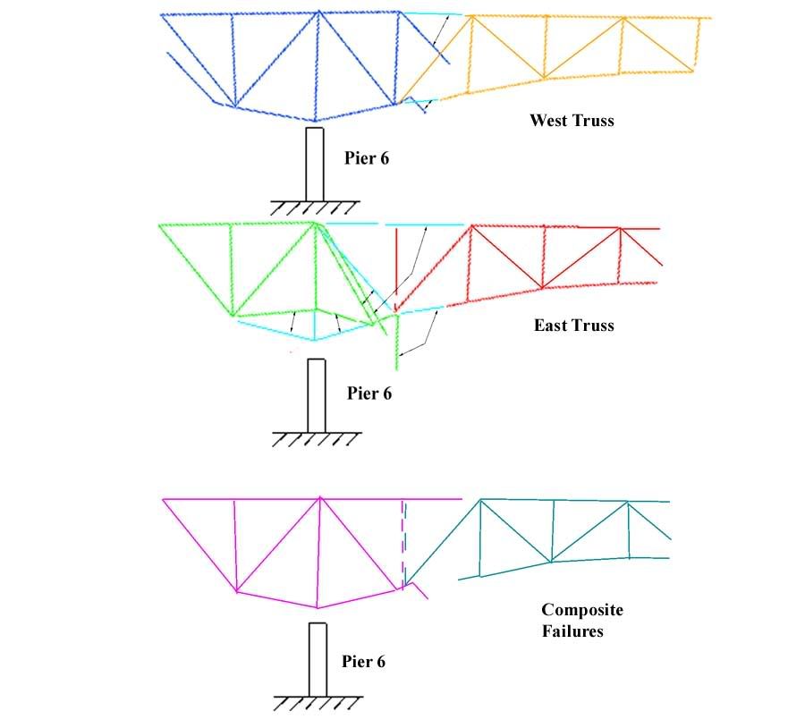
In the above image, Image 9, looking west at pier 6, the two upper panels indicate the west and east trusses, as reconstructed from post collapse imagery, respectively. The blue lines indicate the original positions of members which were located in post collapse imagery, and rotated back into the pre-collapse dispositions.
The lower panel in Image 9 notes the combined post collapse arrangement of both the east and west truss for comparison purposes, and the similarities are striking. With the exception of the U7-L7 strut, the first vertical truss member north of the pier 6 kingposts, both trusses apparantly failed in near identical manner. Noteworthy points of similarity include the U7-U6 top chord severance locations near the U6 connection gusset, the bending moments impressed on both east and west U7-U6 top chord members, the severance locations of both east and west truss L7-L6 bottom chord members, and the bendimg moments impressed on same, and the catastrophic failure at the west truss L7 gusset, specifically the tension and bending loads imposed on the L7-U6 compression diagonal mentioned earlier, which coincide with the apparant severe moments imposed on the east truss's coincident member.
So far, the discussion here has been limited to empirical evidence and my interpretation of same. This is as far as my analysis allows me to proceed without supposition and speculation, however, I am reasonably confident that additional analysis is at least within the bounds of probability and possibility regarding the failure of this bridge.
Put another way, the conclusions I am about to draw cannot, as yet, be substantiated in fact, but neither can they be refuted by the evidence availabe to us at this time. They are well within the realm of structural possibilities as we now know them.
From all analysis to date, we have reason to believe that:
1. Most of span 7 separated from the span 7 pier 6 truss panels prior to east rotation of the pier six truss panels.
2. Video analysis of the failure sequence shows the south end of the bridge falling earlier than the north end of span 7.
3. The east truss at pier 6 mosdt likely lies underneath the west truss at pier 6.
With the benefit of newly discovered data as outlined in this discussion, I offer the following tenative, additional conclusions.
1. Both east and west truss L7-U6 compression diagonals were subjected to severe tensile and bending stresses and shattered near the L7 connection gusset.
2. Both east and west truss U7-U6 top chords were subjected to tensile stresses at or above failure levels early in the collapse progression resulting in separation at or near the U6 connection gusset.
3. Both east and west truss L7-L6 bottom chords were subjected to severe stresses at or near the L6 connection gusset, and both were subjected to bending moments consistent with failure level gravity loads about the L7 connection gusset.
Based on these tenative additional comculsions, I believe it most likely that the east truss U7-U6 top chord failed in tension at or near the U6 connection gusset very early in the collapse progression, quite possibly as the collapse sequence initiating event.
If in fact this key structural member failed as discussed above, a progressive collapse sequence could ensue as follows:
With the east truss top chord severed at U6 as shown in Image 10 above, externally imposed tension loads on U7-U6 go to zero, while internal stress on this member predominates. The upper face of this box beam goes into radical tension while the lower face goes into compression, inducing a bending moment at connection U7, 100% consistent with the post collpase disposition of this member. A similar progression is imposed on the L7-U6 compression diagonal.
Both live and dead span 7 gravity loads are almost immediately transferred to the east truss L7-L6 bottom chord, imposing internal stress on that member similar to that discussed above. It cannot resist the imposed stresses and begins to deflect downwards, as shown in Image 10 above and also indicated by red arrow 1 in Image 11 below.
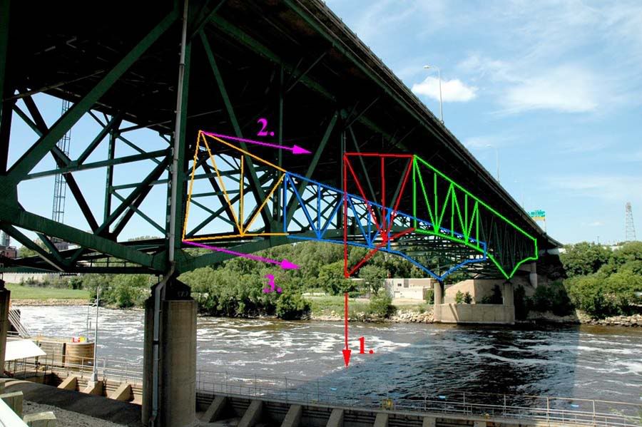
As soon as the east truss L7-L6-L5 bottom chord begins to deflect downwards, significant tensile loads are applied to the horizontal and diagonal sway bracing members at the U6-L6 interface, as indicated by orange arrows 2 and 3 in Image 11 above. These tensile stresses are transferred to west truss members at the swy brace connection points, and are resisted by the both the west truss roller nest/rocker bearing assempbly atop pier 6, and by sway bracing in the horizontal planes co-planar with the west truss top and bottom chords. The vector pair of eaastward tensile stress, and westward resistance to same induces an eastward rotational moment about the west truss bottom chord, transverse (laterally) to its axis.
This rotational moment of the west truss top chord towards the east is transmitted to the now separated pier 6 panels of the east truss via the much more substantial sway bracing atop pier 6 as shown below, by red and orange arrows 2., in Image 12. Both the southwest and southeast kingposts at pier 6 are now in rotation to the east. The main portion of span 7, no longer attached at the east truss top chord, and probably not at the west truss top chord, is subject to much less eastward deflection, by virtue of their bottom chord only attachments to the rotating pier 6 superstructure, however, this rotation imposes severe twisting stresses on both the east and west L7-L6 bottom chord members, again 100% consistent with post collapse imagery data.
Not too far into the rotational failure of the pier 6 superstructure, both bottom chords separate at the L6 connection gussets, and once unsupported at their midspan ends, are nearly severed or completely severed at the L7 connection gusset, 100% consistent with post collapse imagery.
From here, the collapse progression holds little surprise or ambiguity. The pier 6 superstructure continues to rotate eastward, and the rest of span 7's trusswork and road deck, severed from the pier 6 truss panels and unsupported at their south ends, drop straight down into the river. At some point during the sequence, span 6, south of pier 6, having lost the counterbalancing weight associated with the span 7 cantilever compenent, begins to deflect downwards, sagging at midspan, and inducing a smaller but significant rotation to the pier 6 superstructure. This induces the tops of the pier 6 kingposts to rotate a small distance to the south, resisted by the pier 6 roller nest assembl;ies and rocker bearings, and ejects the pier 6 roller nest and rocker bearing components northward from their pro-collapse positions atop pier 6, consistant with their post collapse disposition as evidenced by the available imagery.
Finally, I would repeat that while I cannot prove this is the correct failure sequence, I can say that this sequence is consistent with all available data of which I am aware, and that none of the available data contradicts these assumptions, conclusions and speculations to any appreciable extent of which I am aware. More as new information or imagery becomes available.
Feel free to distribute this analysis for any non-commercial purposes, though I do ask that Free Republic be referenced in all such distributions. All imagery used in this analysis was accessed in the public domain, though original copyrights still reside with the original owners or their designees. Overlying graphics analysis may be distributed for non-profit purposes, with Free Republic referencing as outlined above.
I greatly appreciate all who have contributed to previous discussions regarding this matter, you are too numerous to name but you know who you are. Without your efforts in analyzing this failure, and in bringing imagery and video to my attention, none of this discussion would have been possible.
Thank you.
TOPICS: US: Minnesota; Your Opinion/Questions
KEYWORDS: 35w; analysis; bridge; bridgecollapse; collapse; disaster; engineering; highways; i35; minneapolis
Navigation: use the links below to view more comments.
first previous 1-20, 21-40, 41-60, 61-79 next last
To: jeffers
Wow. Thank you for this wonderful service to FR.
41
posted on
08/21/2007 9:33:47 PM PDT
by
EternalVigilance
(States' rights don't trump God-given, unalienable rights...support the Reagan pro-life platform)
To: jeffers
Thanks for the ping jeffers. I can’t believe how small the point is between the truss (?) and the cement post. Hope they get to work soon on the Cayuga and Lafayette bridge!
To: jeffers
Thanks for keeping us posted.
So bird droppings and road salt corrosion did not play a part?
BTTT
43
posted on
08/22/2007 1:26:31 AM PDT
by
XR7
To: IncPen
To: jeffers
Great analysis--thanks for piecing it all together. You've certainly nailed the point, mechanism and sequence as to how the main span failed.
Couple Qs.
* If you're feeling motivated (insomnia, perhaps), could you redraw that MnDOT diagram so it shows the whole bridge from one side to the other--I'm still never quite sure which are the center spans and which are the landside-spans. And identify what the "king truss"--I'm not sure what a king truss is on a cantilevered tower.
On the diagram, I'm thinking the L9/U10 member on the MnDOT diagram is actually compression, not tension (a typo for MnDOT's consultant). (like the L7/U6 member). For one thing, the photos show it as being a box beam, not an I beam. For another, the bridge wouldn't stand up if it was tension.
* Do you have an opinion as to whether the U10/L10 area failure was or wasn't the initial failure? If the south landside span failed, the center span would be expected to sag and buckle somewhere, is U10/L10 as good as any spot for that?
i.e. if the south landside arm failed somewhere, then the counterweight would be gone from the main span, and the section from U8 to U10 would suddenly be acting in compression, rather than tension. and you'd get a buckling of the tension member somewhere on that stretch, quite possibly at the farthest-extremity of the tension member.
To: jeffers
46
posted on
08/22/2007 3:10:56 AM PDT
by
PogySailor
(Murtha'd: To be attacked by a corrupt politician for doing your job.)
To: jeffers
To: jeffers
Here's a few more thoughts:
Check out my diagram below--do I have the labeling right? Now it's a lot easier to talk and see at the same time.
Now, let's establish how the bridge stands up.
* Cantilever bridges are built out from the piers. Chords on top are tension, chords on bottom are compression.
* Truss bridges are built from pier to pier, tension on the bottom, compression on top.
* A Cantilever bridge with a suspended truss span has cantilever arms reaching out from the piers, then a truss span hanging from the ends of each cantilever span.
So, the tension/compression diagrams in the MnDOT doc show that this is a cantilever bridge with a suspended truss span. There's a bit of overlap between the two span types, as can be seen in this labeled diagram. The Cantilever extends out from Pier 6 from U12 to U6, with the compression chords from U12 to U10 and U6 to U4 acting as tension chords. Similarly, the Truss Span extends from L9 to the L9 on the other side of the river (same spot, other side), with the L9 to L11 compression chord also working as a tension (the entire span, except that last 40' segment from L8 to L9 at each end). (Of course, if my whole diagram is backwards, it makes perfect sense, with U6 to U2 and L5 to L1 as "reversal members" -- able to function both ways).
Now, look at where Jeffers determined the failure occurred. U10/L10. It's right at the outer extremity of tension members on the top chord. And, in the video, it looks like the failure at the north end also occurred right at U10/L10.
Now, imagine (hypothetically) the center span standing without the side spans. It now has to function as a truss span, compression across the top, tension on the bottom. What will fail? The compression members on the bottom will probably function pretty well as tension members, they're big and beefy. But the tension members will buckle under compression.
So, I'm thinking, the south arm may have fallen first. Jeffers is exactly right on how the main span fell, but I think the south span triggered the main span. (Mainly because it fell so crooked while the rest of the structure fell straight. With a long, complex set of spans like this, span like this, you'd expect a point failure somewhere to take out one span in an asymetrical way, then the other spans to fall like dominos as they lose their counterbalancing cantilever arms, and the girder spans on each end to be yanked off their piers or shoved off their piers as the main spans go).
So, Jeffers is right on the main span, and this is why.
The south cantilever platform, from U12 to U4, can stand on its own only if its balanced. If, say, the south half (landside) was to collapse, then an unattached north side of the cantilever platform would simply dump itself into the river.
And, the north side, attached to the suspended truss and whole north cantilever platform (over pier 7), wouldn't simply dump itself into the river, it would try to act as a truss span, from pier 6 to pier 7. But, this isn't going to work. It's not designed to hold up that way--it would need a truss network with a continuous compression member across the top. Which it doesn't have--it's tension from U10 to U8. The truss system is fine, actually, from L9 to L9 across the river. But not from L8/U8 to L8/U8.
So it will fail.
Where will it fail?
The tension chord from U10 to U8 will buckle. Crunch. Game over. Which is exactly what you've shown, Jeffers, and the video clip shows happening on the other side of the river.
So, it could have been an initial failure on U10, south side. But, you'd think that would have resulted in the main span twisting much more as it dropped. As it is, it fell pretty flat. It seemed to take a few seconds for things to fail. Maybe those tension members handled the compression for about 5 seconds as they slowly got bent out of shape and twisted apart. That's how long it took the same failure to occur in the north landside arm.
So, seems to me, it's much more likely that the initial failure was indeed in the south landside span. Between Pier 6 and Pier 5. Something happened on one side or the other, the west side?? since the deck seems to have flopped to the east. Then the east truss/cantilever arm held for the same 5 seconds, and failed. That makes for the twisted deck. And something in there should also account for the rotating king posts. If the west side, south arm failed (around, say, U6 or U4), then the king post would still be intact. Not sure on the rotational movement, but there's probably a few good reasons.
This brings the initial failure back to a small member somewhere, rather than a massive failure of a main structural member, with a result in s similar failure on the other truss arm, which seems more plausible overall to me.
Hope this makes some sense, I'm staying up *way* too late...
Kwuntongchai
To: kwuntongchai
And, as to what happened? This photo http://www.flickr.com/photos/s4xton/981290582/in/set-72157601157770382/
might explain something. Why is the location the girders buckled **behind** the pier? You’d think they’d have bent right on top of the pier. It’s not exactly normal for a girder to bend a couple feet out into the span.
It looks like a compression buckle. They got shoved, and bent out of shape? What shoved them, why? Did the whole south landside cantilever arm (U8 to U1) bust loose off Pier 5 because of expansion joint issues and crush the approach span?
There needs to be some explanation of this, curious as to what anyone thinks. This is the spot directly “in front” of the burning Tastee Truck and schoolbus.
To: kwuntongchai
One more bit, here's a diagram of how a cantilever with a suspended span works.
The mens' arms are the tension members, the sticks are the compression members. In my diagrams above, red are tension, blue are compression, and green function as either compression or tension.
So, the failure mode I'm thinking is that, say, the guy on the right looses his grip on his stick with his left hand. What happens? the weight in the middle will make him tip inward, causing a complete failure. How will the middle section fail? The right guy tips inward, everything pivots where left guy and right guy's hands meet middle guy. Depending on the strength of middle guy's connection to left guy, he will either hang and dangle from left guy and pull left guy into the river, or (in the 35W case) bust loose from left guy and drop more or less straight down.
Meanwhile middle guy's falling has town loose left guy's right hand loose from the stick, and the stick drops, then left guy tips over to our left.
(Also, the buckle in the girders on the approach span, now that I look at it, appears to be too uniform from left to right to have been caused by the twisting south span... Must be some artifact of how a continuous girder bridge buckles over an intermediate pier if it loses one abutment)
To: Congressman Billybob
Thanks for the kind words, but I’m not a licensed engineer. I studied CE for a couple years, but financial pressures forced me into full time employment in construction field management. I put 20 years into that, another ten into computers after a fall broke three vertebra, and am now happily retired. If something interesting comes along, I consider it, but mostly engage in private research.
There are more images and more logic as to the mechanics of this failure, but the good engineers can usually look at the rubble and figure out what puzzles them, while the non-engineers don’t need technical gibberish, so I decided to cut it off where it sits now.
There are good reasons why I’m not considering an approach span failure as the trigger event anymore, and other reasons why I see a center span failure further north of pier 6 to be less likely, but so far everyone seems to follow this well so unless questions are raised, no need to delve deeper into the arcane.
Some professionals have weighed in on this thread, others are considering the material and have yet to air comments, it will be interesting to see where the consensus, if any, lies.
Thanks again for your comments and I hope you keep up your own brand of first class work.
51
posted on
08/22/2007 5:58:29 AM PDT
by
jeffers
To: raybbr
I have seen claims that materials and heavy equipment were stored on the bridge, but I can’t say I’ve seen proof of this.
I recall one image showing small, maybe a little bigger than golf carts, buggies for carrying sand or gravel, some images of men with jackhammers breaking deck for replacement, and maybe one or two dump trucks, but that’s all I have photo support for.
I’ve looked for piles of gravel or sand in the post collapse imagery and have not found them. Not saying there weren’t any, just that so far most of the evidence supporting heavy materials and equipment stored on the bridge, from what I’ve actually seen, is hearsay only.
52
posted on
08/22/2007 6:04:35 AM PDT
by
jeffers
To: PA Engineer
PA Engineer wrote: Based on these tenative additional comculsions, I believe it most likely that the east truss U7-U6 top chord failed in tension at or near the U6 connection gusset very early in the collapse progression, quite possibly as the collapse sequence initiating event.
Have you been able to correlate this with the reported gusset corrosion (pictures) in the MDOT report? I have to head out and will check the replies later. Thanks.
******************
Closeups of the east truss top chord indicate it fractured just into the gusset assembly, but it's hard to see whether this occurred in the bolt array or just south of it.
The viewing angles aren't the best, mostly with the top face broadside to the camera, and the east and west faces edge on to the camera, but there is clearly a straight line demarcation where the green paint ends and heavy rust begins.
Other images of other members show black paint where the gussets were, but my gut feeling from looking at the inmages is that the visible fracture took place just inside the southern edges of the U6 gusset.
If you twist my arm, I'm liable to even say it let go at the first bolt line in the array, but that's because I can deny all claims made under duress.
Like you, I haven't been ignoring NTSB's claim of a "gusset design error". At the time it was issued, someone looked at the blueprints and said "Whoa! This is not good!". It's not a statement to forget about, but the images make it hard to say for sure.
Here, what do you think?
53
posted on
08/22/2007 6:47:18 AM PDT
by
jeffers
To: TXnMA
TXnMA wrote:
“...I do notice
some very early-on buckling of the main-span western lower chord — right at the nothern pier end......”
***********
The bottom chords in the first three truss panels on either side of piers 6 and 7 are integral parts of the cantilever component of this bridge’s truss design. They are in compression, where simple truss design would have them in tension.
Because it wasn’t a pure cantilever design, however, those members are nowhere near stout enough to carry the bridge by themselves.
Sever span 7 just about anywhere along its length, and those bottom chords will go into compression orders of magnitude beyond design limits and buckle almost immediately.
If you see that in differential frame analysis, it is expected and supports the contention that span 7 was severed early in the collapse sequence.
Looking forward to your analysis.
54
posted on
08/22/2007 6:55:57 AM PDT
by
jeffers
To: norwaypinesavage
I think fatigue played a critical part in this collapse, and as a result, find it hard to look away from the U6 gusset area.
At that point, the top chord goes into reversal from being in tension nearer the south piers. It’s carrying the upper end of the U6-L5 tension diagonal, and the upper end of U6-L6 also in tension. Further, its got the upper end of the L7-U6 compression diagonal.
There’s many opposing forces coming together at that critical point, and repeated loading and unloading of the span over decades of carrying traffic essentially have to focus fatigue inducing alternating and differential stresses there.
55
posted on
08/22/2007 7:06:54 AM PDT
by
jeffers
To: jeffers
56
posted on
08/22/2007 7:09:30 AM PDT
by
KC Burke
(Men of intemperate minds can never be free...their passions forge their fetters.)
To: dr_lew
dr_lew wrote: Excellent. I was thinking along these lines, but in a vague sort of way, and I was losing concentration.
I had found those two photos you have here by Noah Kunin. These were taken minutes after the collapse, before any emergency response. ( The one with the roller on the ground is falsely credited in at least one FLICKR page. ) Note the driver being helped from the maroon car in the second photo, taken from about the same spot. Kunin has an earlier photo showing the guy in the yellow bicycle helmet about to venture out onto the collapsed approach.
In the one with the roller, you can see the ladder cage that I think is on L6-U6, visible in your reconstruction diagrams. Isn’t that right? When you say “kingpost” do you mean the L8-U8 vertical element? I thought this was L6-U6, as I say.
Also, you have the top chord mislabeled as U8-L7, when it should be U8-U7 ... a typo, right? This is in the “maroon car” photo.
I was thinking that the truss above pier 6 must have rocked back to the south, analogously to the north side behavior at pier 7, and this is what “kicked” the roller bearing parts to the north, and its what caused the rotation of the roadway back and to the east.
Anyway, I think your analysis is very close to the actuality. I saw a news item about the gusset “design flaw” that singled out U6, or maybe U10, which corresponds to U6. I got the idea that this “discovery” had to do with failure to account for bending moments applied to the gusset by relaxation of the framework.
So, thanks, and great work.
**************
Thanks for attributing those images to Noah Kunin. While keeping track of open source versus private sources in the imagery, I had lost track of specifically who caught which image, and appreciate you helping Mr. Kunin receive due credit. The bicyclist also deserves credit for helping the lady driving the maroon car. That's a steep slope leading to the edge of a bridge deck that just collapsed, and he indeed sucks it up and goes down there to help the lady wearing the beige pants with the black purse. I suspect there were a lot of heroes who's efforts that day will go unrecognized.
Yes, the U8-L7 label on the top chord is a typo, as noted in the post immediately preceeding your's. Sheer luck got me in ahead of your observant catch. It should read U8-U7 as you note.
"Kingpost" may not be the proper term for this truss design, but many of us looking into this failure have been using that term so long it has become shorthand. Yes, it does refer to the vertical elements directly above the piers, in this case, U8-L8.
I can see how you could have thought U8-L8 was U6-L6. As the image below shows, there was a ladder cage attached to the vertical strut at and just above L6.
However, as the image also shows, there was an additional ladder cage attached to the sway bracing between the east truss and west truss U8-L8 members too.
It is my belief that we see the latter of the two cages in the referenced images, because the sway bracing members, as denoted by the green arrows in the image below, are clearly visible in those post collapse images, and even appear to be attached to the ladder cage in question.
I fully agree with your assessment of the forces which kicked the rocker plate and roller bearing out from under the superstructure to the north.
Two obvious ways this could happen. One, loss of the span 7 cantilever element could allow span 6 to sag and rotate the pier 6 trusses southward at their upper extents.
Two, failure in the span 7 top chord(s) would transfer tensile stresses rapidly to the bottom chords, previously in compression. The bottom chords from L8 to L5 were pushing south on pier 6 just prior to the collapse, and severing the span 7 top chords would generate a powerful jerk on those members, into sudden tension, pulling the pier 6 bearing assemblies northward.
Of the two, I favor the second. From the pier 7 imagery on the north end of the river span, we see that sagging in span 8 raised the severed ends of the pier 7 span 7 trusses high above their original positions, yet in the collapse video, we do not see the close end of span 7 raised in this manner or to this degree, in fact, we only see it drop from its pre-collapse level.
That strongly tends to rule out a span 6 failure early in the collapse sequence, at least before span 7 separated just north of pier 6. Any axial rotation of the superstructure about the top of pier 6 would have had to come after span seven severed, or would have had to be of small magnitude if occurring before span 7 fracture. Otherwise, we'd see span 7 go up at the near end in the video, before dropping down.
A sudden yank on the bottom chords also, circumstantially at least, supports early top chord failure in the first two panels north of pier 6. The bottom chord goes into reversal north of L5. A top chord failure here or northward would not impress as large or as sudden a change in the state of the bottom chord out past L5 as it would south of L5. Thin, I know, but pointing in a consistent direction at least.
Thanks again, for your knowlegable comments and for catching my typo.
57
posted on
08/22/2007 7:43:38 AM PDT
by
jeffers
58
posted on
08/22/2007 7:43:49 AM PDT
by
Godzilla
(Pride is what we have. Vanity is what others have.)
To: XR7
XR7 wrote:
Thanks for keeping us posted.
So bird droppings and road salt corrosion did not play a part?
***********
I’d guess road salt corrosion and possibly bird droppings probably did play a part, but it is impossible for me to say how large of a part at this point.
Regardless of where the triggering failure took place, metal fatigue, rust, corrosion and cracked welds would not have helped the bridge carry its gravity loads. But pinning the failure to one specific cause of weakening is beyond my ability.
Jim Trent has favored corrosion fatigue and cracking as significant causal factors in the past, and I tend to agree with that assessment, in theory at least.
I don’t have empirical data in this case to assess causes of component failure, but anything that weakens steel in fracture critical structures can’t be viewed as beneficial, whether the structure fails or not.
59
posted on
08/22/2007 7:52:52 AM PDT
by
jeffers
To: kwuntongchai
kwuntongchai wrote:
Great analysis—thanks for piecing it all together. You’ve certainly nailed the point, mechanism and sequence as to how the main span failed.
Couple Qs.
* If you’re feeling motivated (insomnia, perhaps), could you redraw that MnDOT diagram so it shows the whole bridge from one side to the other—I’m still
never quite sure which are the center spans and which are the landside-spans. And identify what the “king truss”—I’m not sure what a king truss is on a
cantilevered tower.
**************
I don’t know about drawing the whole bridge. I’ve got a pretty busy schedule right now as it is, and that’d take some time to do. I know once I got into it, I’d start adding more and more detail, until I’d redrawn the full set of working plans, and I’d also veer off into stress and failure analysis such that a project like that might stretch into years.
In your post 45 photo, pier 8 is in color at far left. Span 8 starts there and ends at the next pier to the right, pier 7, the north end of the main river span, span 7. Pier 6 is on the right side of the river, and span 6 stretches right from there to pier 5, the farthest right member you’ve highlighted in color, save for that last diagonal.
(There’s a LOT going on at that diagonal, but that’s another book that isn’t written yet. For now, at least note the expansion joint in the road deck above that far right diagonal.)
Kingpost is a vernacular term we’ve always used to refer to the tallest vertical member in a truss. In practice I and the people I’ve worked with usually used it in connection with Pratt or Howe truss designs, in this analysis, we used the term to refer to the vertical members above piers 6 and 7, on either end of the main river span.
Keep in mind, this truss isn’t a pure cantilever either, it is a complex truss, which is about as far as I want to get into that, absent specific questions.
*************
kwuntongchai wrote:
On the diagram, I’m thinking the L9/U10 member on the MnDOT diagram is actually compression, not tension (a typo for MnDOT’s consultant). (like the
L7/U6 member). For one thing, the photos show it as being a box beam, not an I beam. For another, the bridge wouldn’t stand up if it was tension.
*************
I believe you are almost certainly correct here, except the member in question is L9’-U10’, not L9-U10. L9-U10 would be in span 6, south of pier 6, while L9’-U10’ resided north of pier 7 in span 8.
I believe the origin was designated at the center of the main span, span 7, with normal numbered junctions incrementing south from there, and primed numbered junctions incrementing north from there.
*************
kwuntongchai wrote:
* Do you have an opinion as to whether the U10/L10 area failure was or wasn’t the initial failure? If the south landside span failed, the center span would be
expected to sag and buckle somewhere, is U10/L10 as good as any spot for that?
i.e. if the south landside arm failed somewhere, then the counterweight would be gone from the main span, and the section from U8 to U10 would suddenly
be acting in compression, rather than tension. and you’d get a buckling of the tension member somewhere on that stretch, quite possibly at the
farthest-extremity of the tension member
************
In your later posts, you use a connection labelling scheme inconsistent with that used by MnDot, so I’m not completely sure I know what you ask here.
However, your labelling scheme here seems consistent with the rest of your question, and in any event, a general answer will suffice.
If I was to look for a triggering failure anywhwere on the southern approach, the first, (and possibly last) place I’d look would be at the pier 5 endbeam/crossbeam/rockerbearing assemblies, on both the east and west trusses, the far right diagonal in your image, mentioned above.
A lot of significant history there, and I refer you to the 2006 Inspection Report for more detail before getting deeper into this.
60
posted on
08/22/2007 8:23:14 AM PDT
by
jeffers
Navigation: use the links below to view more comments.
first previous 1-20, 21-40, 41-60, 61-79 next last
Disclaimer:
Opinions posted on Free Republic are those of the individual
posters and do not necessarily represent the opinion of Free Republic or its
management. All materials posted herein are protected by copyright law and the
exemption for fair use of copyrighted works.
FreeRepublic.com is powered by software copyright 2000-2008 John Robinson